
![]()
| Back to main page |
|
| Die LIMUS Umwelttechnik
GmbH hat Ihre Geschäftstätigkeit aufgegeben. Wir von der PONDUS Verfahrenstechnik GmbH möchten Ihnen aber gern weiterhin mit Rat und Tat zur Seite stehen. |
 |
| Wir freuen uns über Ihren Besuch. Sie werden automatisch zu uns weitergeleitet. |
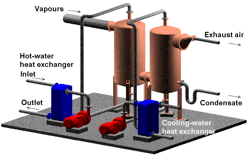
Fig. 1: Model of a vapour condensation system
Vapours arise while the sludge is being dried, and they are also associated with other thermal sludge treatment processes. In all instances the water vapour is mixed with larger or smaller quantities of air. Furthermore the vapour also contains smaller quantities of other substances expelled from the sewage sludge. Prior to their deodorisation it is necessary to reduce the volume by condensing the steam contained in the vapours.
The vapours also contain nearly all the heat consumed for sludge drying. Consequently, it is essential to recover the largest possible amount of this heat for use a second time, thereby increasing operating efficiency.
Vapour cooling condenses the steam and releases the condensation heat. There are two options to use this heat:
Indirectly cooled condensers, e.g. tubular heat exchangers, are unsuitable for this purpose because the vapours from the sludge contain grease, oil and dust which leave a deposit that has to be removed by frequent cleaning.
Contact condensers have proved their worth in this context because the vapours are brought into direct contact with the coolant. Water is a suitable coolant, provided that it contains few hardeners, recooled condensate or sewage sludge.
Vapour condensation takes place in three stages:
A single-stage condensation process is used if the heat contained in the vapours is not to be recovered.
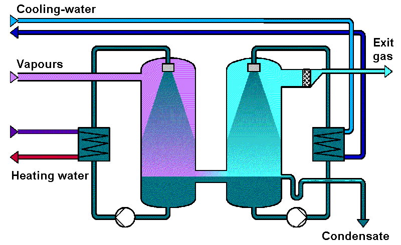
Fig. 2: Vapours condensation with heat utilisation
A two-stage installation for hot-water generation is shown as an example in fig. 2. The principal components are the two condensers where the heat is recovered in the first one, while the second one is used to cool down the residual vapours still further.
In both stages the steam contained in the vapours is precipitated by the circulated condensate which is atomised by special nozzles and pumps and then recooled in heat exchangers. The condensation heat is transferred to the hot-water system of the clarification plant in the circuit of the first condenser. Feed-in temperatures of between 70°C and 80°C are normally achieved, and in special cases even higher. However, the amount of heat that can be recovered diminishes with increasing feed-in temperature.
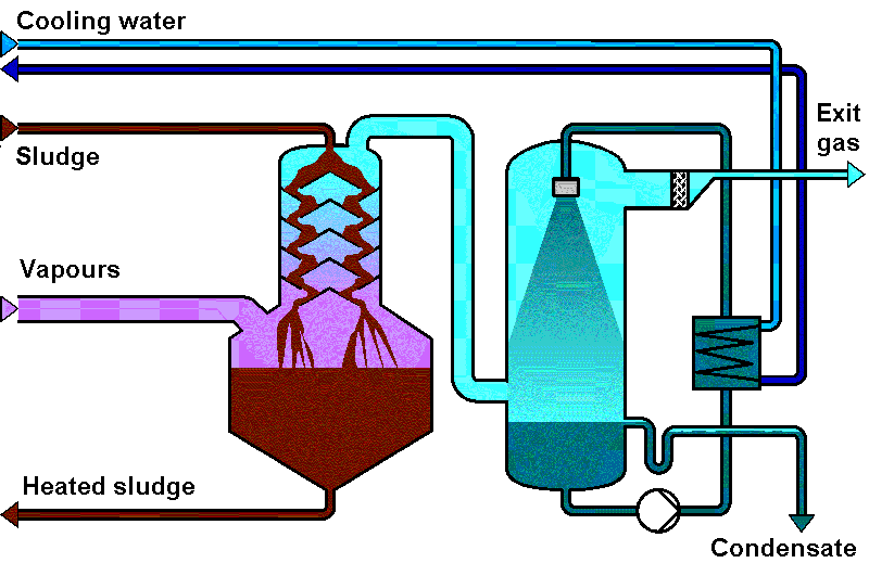
Fig. 3: Vapours condensation with sludge preheating
Fig. 3 shows a circuit in which the waste heat is used for sludge preheating. The sludge is fed into the head of the condenser and flows downwards over the cascades preserving the floccules. The lower section of the sludge contact condenser has been enlarged to the point that it can function as a supply tank for the sludge feeding pumps of the dewatering system.
The second condenser stages usually cools down the remaining vapours to between 30 and 40°C. Excessive condensate flows to the sewage clarification plant. The exhaust air leaving the second condenser contains the non-condensable gases and a very small amount of steam. For complete deoderisation the exhaust air is conducted into the firing chamber of the boiler or into a biofilter for cleaning.
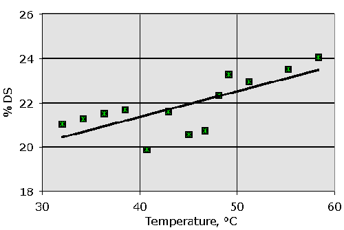
Fig. 4
Fig. 4 shows as dewatering in a centrifuge is improved by preheating of the sludge. In this case digested sludge was treated; deviation of points due to operational fluctuations.
LIMUS injection and sludge contact condensers are made for all capacities encountered in practice. However, a separate condenser installation should be assigned to each drying line.
Amount of recovered heat: over 70% Condensate exit temperature: 30-40°C Hot/warm water temperature: up to 80°C
The stainless steel condensers are operated with a slight vacuum.
The process is characterised by a number of substantial advantages:
- No heat transmitting surfaces, thereby eliminating the need for elaborate heat exchanger cleaning.
- High heat transfer rates and compact equipment as a result of direct vapours condensation.
- Gentle, clog-free preheating of sludge by direct condensation in contact condensers with in-built cascade elements.
- Optimal adaptation to the given use of the waste heat by different circuiting of the condensation stages.
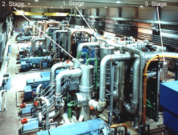
Fig. 5: Three-stage vapours condensation in a large German sewage
sludge drying plant.